Intro
Welcome to my first post on this blog. Today I will be sharing my clock module for the 8-bit computer I am building. The computer is heavily inspired by Ben Eater and his series following the construction of his own. I will also be utilizing the book he recommended: Digital and Computer Electronics by Albert Paul Malvino, Jerald A. Brown.
Outline
For this module my goal was to create a toggle that would allow me to choose between a constant automatic pulse, a manual pulse, and a halt input for much further down the line. To ensure consistent predictable results, all user inputs will be debounced.
Parts List
This module will consist of three NE555 timers, two 74LS00 TTL ICs, three LEDs, a potentiometer, a button, a push button, as well as an assortment of wires, resistors, and capacitors.
The Build
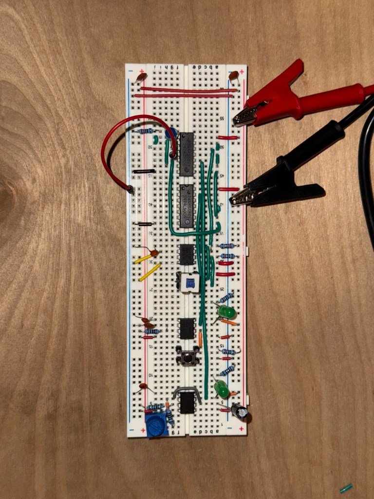
Starting from the bottom we have the astable pulse. Following the first use case (Figure 9) in the NE555 datasheet, you can produce a clock pulse. I added an additional potentiometer for variable speed, though its range proved too limited to be very useful.
Next is the manual clock pulse. This is simply a button that has been debounced using the 555 timer.
Similarly, we have a debounced push button. It would seem superfluous to debounce what is essentially a switch, but it’s actually important. Most switches are designed to be “break before make”. This means that if you push the button just right, there will be a window where neither input is connected. by using the 555 timer in the same way we did with the switch we can prevent the state from changing without forming a new connection.
Logic
Last but not least is the logic that puts the whole circuit together. These two 74LS00s (Quad two input nand gates), can be used in combination with our debounced select. We also want to include a halt input. This same logic circuit can be found all over the internet, but I wanted to blow the dust off of my digital logic knowledge from class a year ago.

When creating a circuit, a truth table is useful to create a “black box”. You know your inputs and you know your outputs, what you need to solve for is everything in between. The Karnaugh map is by far the easiest way to do this. But we don’t just want the first solution we get. We can use the principle of “Every logic gate can be represented by nand gates”. This will significantly reduce the number of ICs we need to use and save some breadboard space.
Final result
After all this we get a beautiful circuit that can switch between a astable and manual pulse.
Of course the circuit never works in the beginning. I worked through each nand output with my multimeter to solve all the missed connections. Also don’t forget that we added a halt! If the circuit doesn’t appear to work and you have the halt low, then it’s actually working perfectly!
Conclusions
Thanks for reading! There will be much more to come. I know the technical stuff was brief but I just wanted to display my progress while adding a couple of useful tidbits. Thanks again!

Leave a comment