Intro
Today I’ll share my recent progress on my 8-bit computer! The progress was made in the form of two 8-bit registers. I’m making the registers before even outlining the bus is because I don’t know the best way to lay everything out yet. Therefore, I’ll continue to build each piece as a module. After every module is complete I will assemble!
Outline
I set out to make two 8-bit registers. I wanted to see the data currently stored in the registers and control the input/output for when we connect everything to the bus. Much more of this module will be temporary. When I show to circuit later on, know that all jumper cables are inputs/output that I don’t/can’t make permanent yet.
Parts List
These two modules require 16 LEDs (preferably homogenous), two 74LS245s (Octal Bus Transceiver), four 74LS173s (Quad D-Type Register), and many wires.
The Build
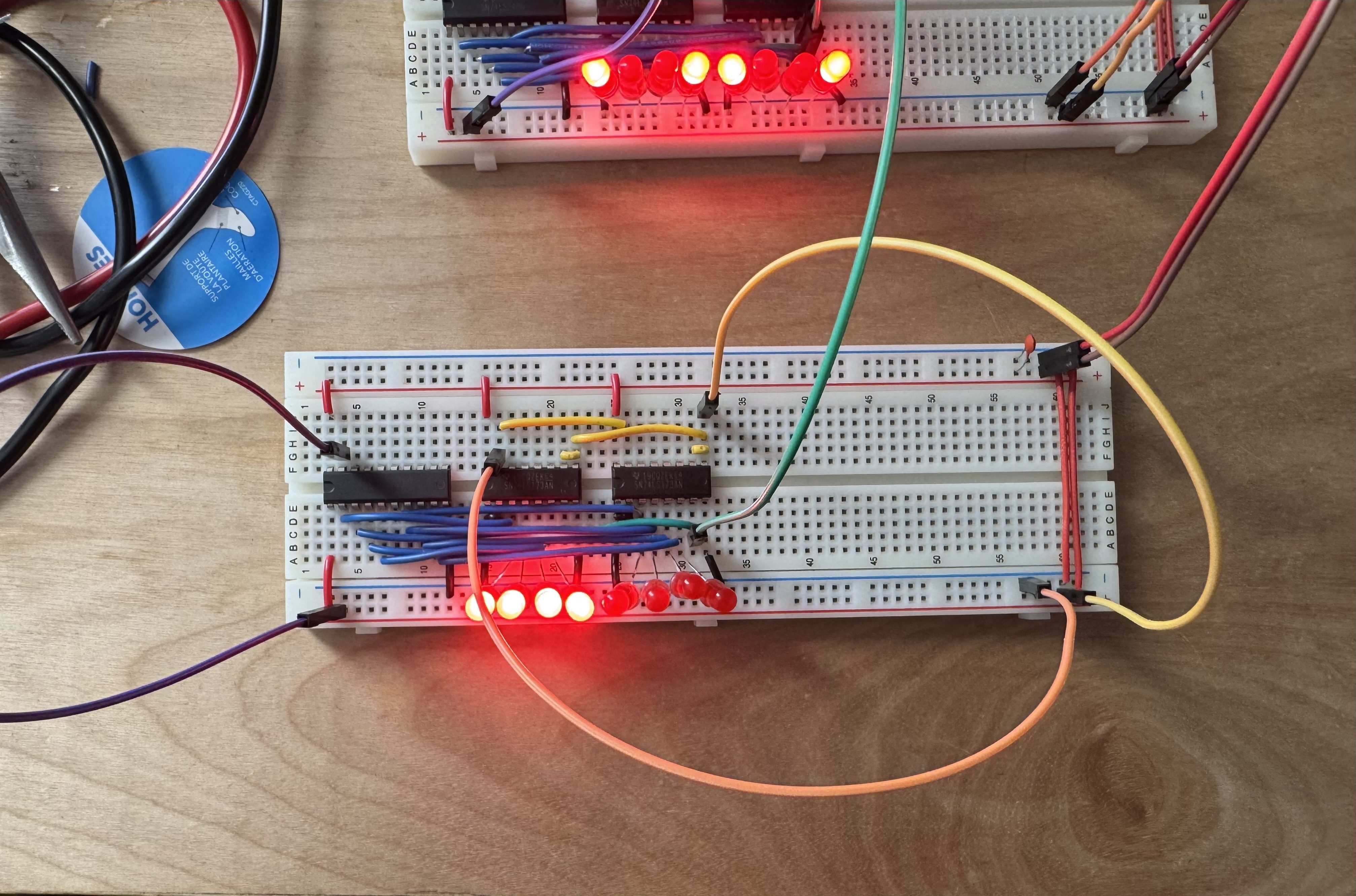
From left to right we have the 74LS245, then the two 74LS173s. I’ve removed the input jumper cables on the top of the 74LS173s to clear some visual clutter.
The control cables are:
- Green: clock
- Purple: output enable
- Orange: clear
- Yellow: load (input enable)
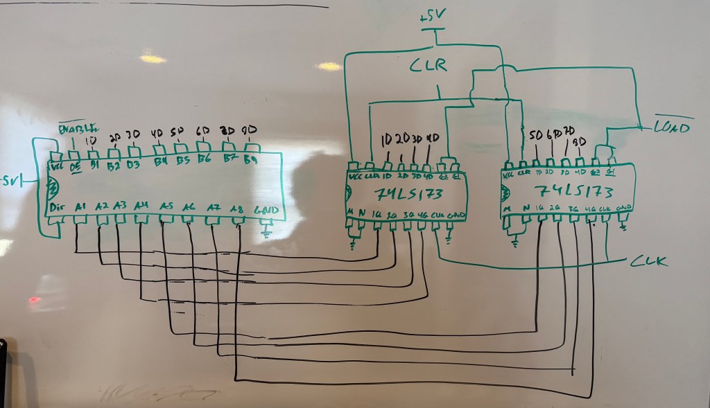
We are using the 74LS245 (on the left) to control the output of the registers. The 74LS173 does have built in tri-state buffers, but we would like to keep track of the data in the registers at all times, not just when outputting. To achieve this we will tie the output enables (M & N) low because they are inverted. We will then just use the 74LS241s enable out. Here’s the complete circuit with both registers, the clock, and all inputs/outputs attached:
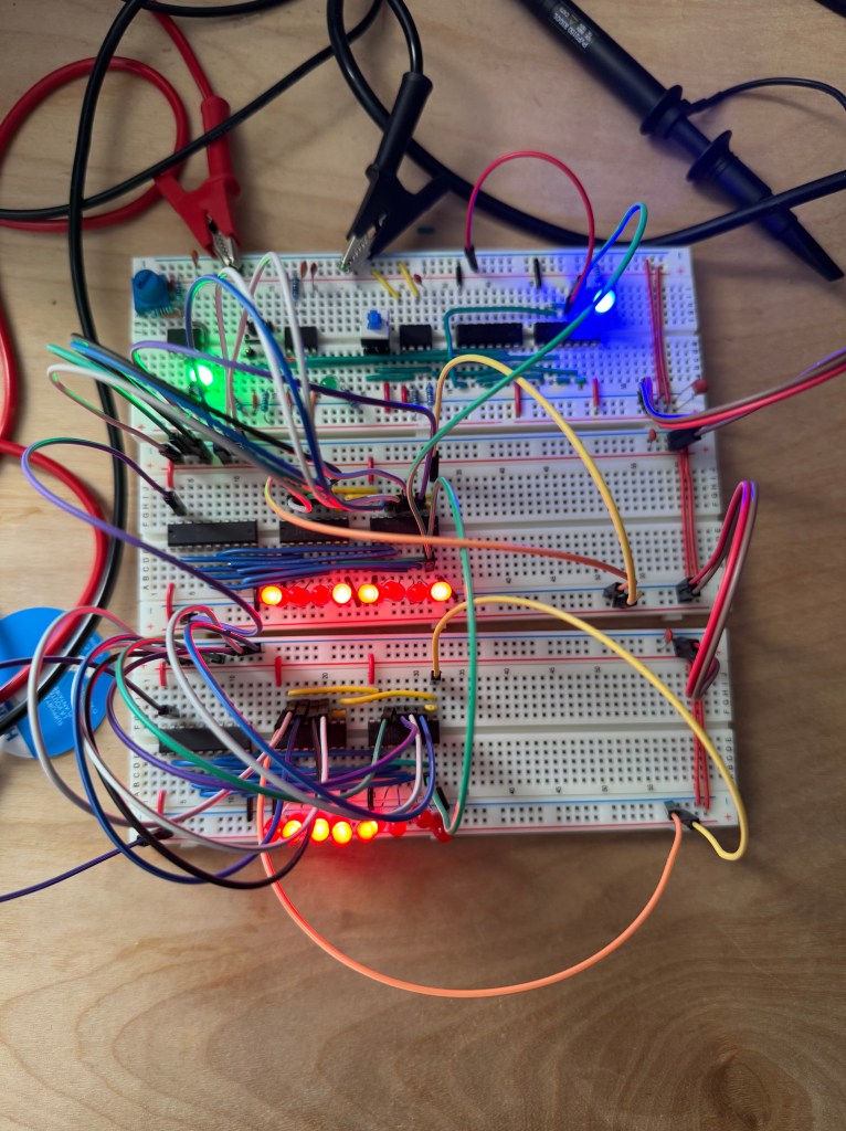
Very messy, but as we finish more parts of the computer, it will naturally neaten up.
Testing
There are two things that I would like to verify.
- Both registers can read/store data
- And registers can write data to each other
Read & Store:
Bus Transfer:
For the sake of brevity I won’t show me testing the other register, but rest assured it works.
Conclusions
Although these circuits were more simple than the clock, I find the results mesmerizing. I got lucky, so there wasn’t any debugging to be done. After familiarizing myself with the input and output I found everything to be in order. What stuck with me is how I was able to use the manual pulse clock module to test. It’s nice to put a previous module to use. Next up is the ALU!

Leave a comment